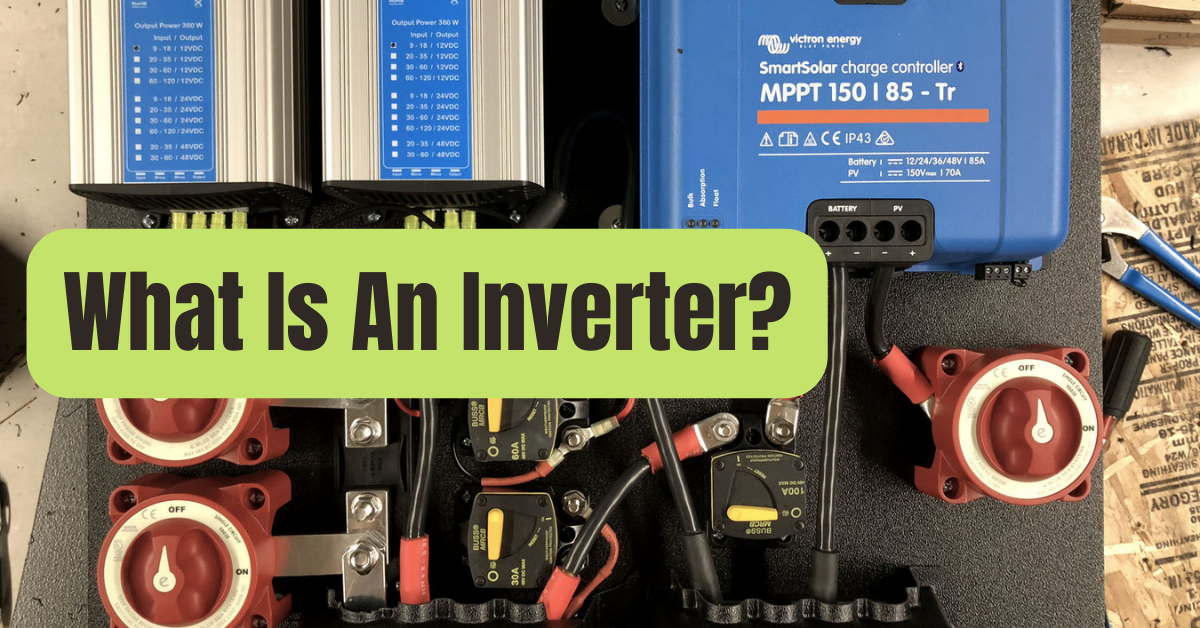
The DC voltage is changed into an AC voltage using an inverter.
The output AC voltage is often equivalent to the grid supply voltage of either 120 volts or 240 volts depending on the nation, although the input DC voltage is typically lower.
The inverter may be designed as a freestanding piece of machinery for uses like solar power or as a backup power source using batteries that are charged separately.
The second arrangement is when it is a component of a larger circuit, such a UPS or power supply unit.
In this instance, the rectified mains AC in the PSU serves as the inverter input DC, while the rectified AC in the UPS serves as the inverter input DC when there is power and the batteries serve as the inverter input DC whenever there is a power outage.
The shape of the switching waveform determines the various kinds of inverters.
These have various circuit designs, efficiency, benefits, and drawbacks.
When powering electronics and electrical equipment qualified for the ac mains voltage, an inverter converts dc power sources into an ac voltage.
They are also commonly employed in the inverting stages of switched mode power supply.
The waveform, frequency, and output waveform of the circuits are categorised together with the switching technology and switch type.
Operation of a Basic Inverter
An oscillator, control circuit, drive circuit for the power devices, switching devices, and a transformer are components of the fundamental circuits.
By transferring energy from a dc source, such as a battery, or from a rectifier output into an alternating voltage, one may convert dc to alternating voltage.
This is accomplished by repeatedly turning on and off switching devices, then scaling up using a transformer.
Despite the fact that there are various configurations without a transformer, they are not often employed.
Power devices like MOSFETs or power transistors turn on and off the DC input voltage while sending pulses to the transformer’s main side.
The secondary winding experiences an alternating voltage as a result of the primary’s fluctuating voltage.
Additionally, the transformer serves as an amplifier, raising the output voltage at a ratio set by the turn-to-turn ratio.
Most of the time, the output voltage is increased from the batteries’ typical 12 volts to either 120 or 240 volts AC.
Push-pull with center tap transformer, push-pull half-bridge, and push-pull full bridge are the three most often used inverter output stages.
The push pull with center tap is the most common design since it is straightforward and always produces the desired results, but it utilizes a larger transformer and is less efficient.
The diagram below depicts a straightforward push-pull DC to AC inverter with a center tap transformer circuit.
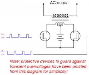
Figure 1: Basic inverter switching circuit
Waveforms Produced By Inverters
The three most popular kinds of output waveforms for inverters are the square wave, the pure sine wave, and the modified sine wave.
Although the square wave is straightforward and less expensive than the other two, it has a lower power quality.
The modified square wave is appropriate for most electronic devices and offers greater power quality (THD45%).
These feature rectilinear pulses with dead areas in the middle of the positive and negative half cycles (THD about 24 percent ).
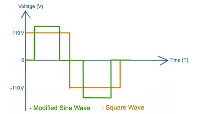
Figure 2: Modified sine waveform
The optimum waveform, with a THD of roughly 3 percent, is produced by a genuine sine wave inverter.
It is the most costly, however, and is used in devices like laser printers, stereos, and medical equipment that need sinusoidal waveforms.
These are also used in inverters and other equipment that is linked to the grid.
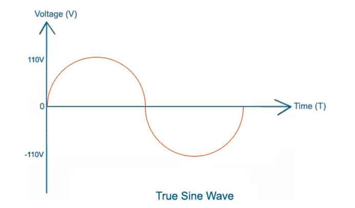
Figure 3: Pure Sine Wave
Applications
Applications for inverters include anything from tiny automobile adapters to home or business uses and huge grid systems.
- Discontinuous power systems
- As independent inverters
- Regarding solar power systems
- Being a component of a switched mode power supply

